TIPniques: Parametrics in AutoCAD, Part 2
Last month we took an introductory look at Parametrics in AutoCAD. I want to continue that look, but in more depth. It’s one thing to know that commands and features exist inside AutoCAD or any other program, but it’s a completely different thing to know how and when to use them. Knowing "why" doesn’t hurt, either.
Geometric constraints
Geometric constraints are associations and restrictions based on geometric principles. AutoCAD can apply geometric constraints to 2D geometry. Two objects are constrained to each other in a specific way. Objects can have more than on constraint. For example, if a square is drawn, all four sides must be equal in length and each leg is perpendicular to another. These geometric aspects can be constrained to ensure that the linework remains a square.
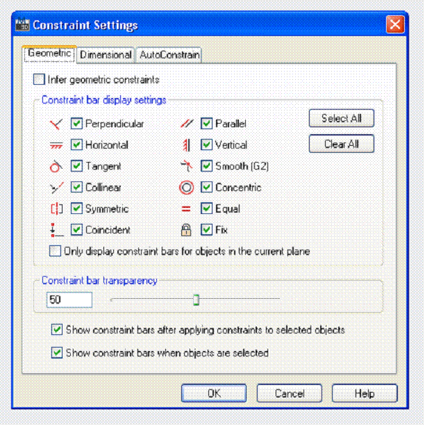
Figure 1: The Constraint Settings manager. Select which constraints will be applied via Auto Constrain. It also gives you a list of what constraints are available.
There are several ways to geometrically constrain a square. One requirement is to make the sides equal. Just two sides - one on top and one on the side. This ensures that these two lines stay the same length. Lengthen one and the other changes to match the first. Make one angle perpendicular - it doesn’t matter which one. Then make opposite sides parallel. What regulations determine if a polygon is a square? Use those geometric constraints.
Applying constraints
There are several ways to apply geometric constraints. One way is to manually apply them. Go to the Parametrics tab on the ribbon to get access to the parametric commands. The Geometric panel has all of the constraints. Click the appropriate icon for the type of geometric constraint you want to use. To make two sides of the square parallel, select the parallel icon, pick the first line, then the second line. If the second line is not parallel to the first, it will be rotated so that it is parallel when you apply the constraint! This is one way you can ensure your linework is correct. It’s an interesting way to draw, too.
Applying constraints one at a time can be very time consuming. It can also mean that you miss a constraint that you needed. One way to speed up the process is to use the Auto Constrain command. Select this button on the ribbon, then pick the lines that make up the square. The polygon is instantly constrained. It should even be fully constrained. A fully constrained set of objects cannot be constrained any further. AutoCAD will not permit you to over-constrain your linework. It must always have at least one aspect that is not constrained. If you over constrain your linework, an error message will appear and you will need to redo your constraining attempts.
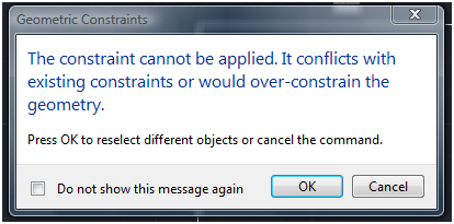

Figure 2: It is not possible to create conflicting constraints. AutoCAD will warn you with this message and allow you to try again.
Auto constraints are applied in a predetermined order. By default, Coincident constraints are applied first. A coincident is where two objects meet. If you would rather the Equal constraint be applied first, then open the AutoConstrain manager and move the Equal constraint to the top. AutoCAD will then look for objects that are equal first and apply this constraint. It then moves on down the list until all pertinent constraint options have been applied.
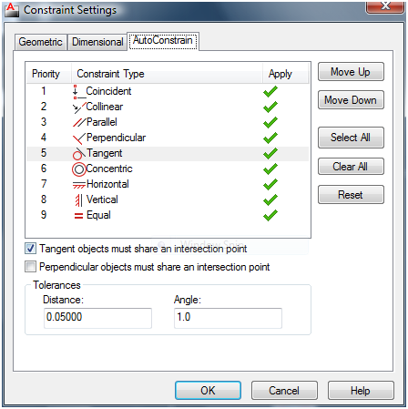

Figure 3: Auto Constrain will apply geometric constraints to the selected linework in a predefined order.
Another method of applying Geometric constraints is through Inferred constraints. This is similar to Auto constraints, excep that they are not applied en masse through a selection set, but instead are applied as you create objects. They also apply constraints differently than the Auto Constrain feature. For example; use the rectangle command to draw a rectangle of any size. Use the Auto Constrain command. Turn on Inferred Constraints by clicking on the Infer Constraints icon in the status bar on the far left. It can also be turned on by selecting the check box in the Constraint Settings manager in the Geometric tab. Use the Rectangle command again. Notice that the constraints are similar, but slightly different. Now use the line command with Ortho on (press F8 to toggle Ortho on/off) to create a rectangle. The geometric constraints that are applied by inferred constraints is very different this time. Inferred constraints apply constraints as you draw. That means it is much more likely to apply a coincident constraint when one or more line segments are created.
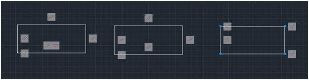

Figure 4: The rectangle on the left was constrained with Auto Constraints. The center with Inferred Constraints. The shape on the right was drawn with the line command with Inferred Constraints turned on.
As you draw, design, and create your model, use Inferred Constraints to apply Parametrics as you go along. If they get in the way or constrict your design process too much, turn off Inferred Constraints and apply them afterwards. Removing Constraints is one way to deal with pesky constraints. Select the constraint glyph and press the Delete key. There is also a Delete Constraint button in the ribbon. Select it, then select the object that is constrained. You can hide the constraint glyphs too. Click the X on the right of each glyph. This doesn’t delete the constraint; but hides it so it doesn’t clutter the screen.
You can also “relax” a constraint so you can edit the constrained linework. Select the object or grip of an object and press the CTRL key. This will “release” the constraint so you can edit your object. Once you finish the constraint will be reapplied. If your changes mean the constraint is no longer valid, it will be removed.
Conclusion
Geometric constraints control and influence the linework of your 2D model in AutoCAD. They ensure your objects geometric relationships remain intact. Your design stays the way it was designed. You can apply these constraints in many different ways; automatically, by a selection set, or one at a time. Your choice.