TIPniques: Freeform Modeling in AutoCAD 2010
AutoCAD has been able to work in three dimensions for a very long time. But this hasn't always been easy to do. AutoCAD 2007 made great strides in AutoCAD's 3D abilities. AutoCAD 2010 has made working in three dimensions even easier, not to mention more powerful.
We have been looking at the new features in AutoCAD 2010 for the last couple of issues and this month we will finish that discussion. Last month we explored the 3D Gizmos that were added in the latest release of AutoCAD. They make navigating and working with 3D objects much easier. AutoCAD 2010 makes a big move deeper into the world of 3D modeling by giving us the ability to use freeform modeling techniques.
What is freeform modeling?
Freeform modeling is a process of creating and manipulating three dimensional objects in a more organic way. The surfaces comprise more vertices. This fact allows us to have more control points to work with. The more vertices in an object, the more you can do with it. The more there are, the smoother an object can be. With Freeform modeling, you are more "free" to manipulate the model as you desire.
Previous versions of AutoCAD depended on the use of primitives, lofts, revolutions, sweeps, and other basic forms of model manipulations. They were static and "non-organic" in nature. We were limited in what we could design. But now AutoCAD 2010 gives us the ability to use MESH modeling tools along with our primitives. These tools and methods give us more vertices to work with, which in turn allows us to use the new gizmos on these vertices to create things that would have been impossible to consider in previous versions.
The Mesh Modeling ribbon tab
If you want to begin your model using the freeform mesh modeling, where do you begin? Anywhere. What do you want to create? Start with a shape that is close. Once you start, you can make it a mesh, smooth it, crease it, and more. Or you can start with a mesh based primitive shape (box, cone, sphere, etc.) Either way, you can always make the item a mesh.
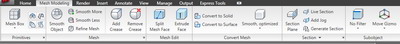
Figure 1: The AutoCAD 2010 ribbon has a Mesh Modeling tab. Access it in the 3D Modeling Workspace.
Mesh primitives
These are very similar to the standard primitives to which we are already accustomed. If you wanted to create a basic table consisting of a top and four legs, you can use primitives. The "old" or standard primitives can very quickly create a table as shown in Figure 2. I used the box primitive to create the top and legs.
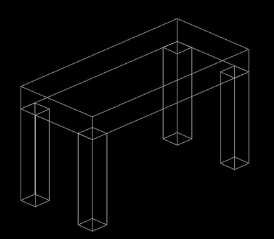
Figure 2: A simple table created with standard primitives.
If we used Mesh Primitives, (the mesh box primitive), we would get what is shown in Figure 3.
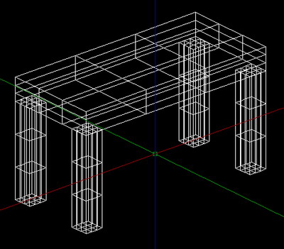
Figure 3: A table similar to that in Figure 2, but created with mesh box primitives.
Right away you can see the main difference between the solid objects in Figure 2 and the objects in Figure 3. The Figure 3 objects have more tessellation - or more vertices and edges. When you create a mesh primitive, you can set the range of tessellation beforehand. When you convert an object to a mesh, you can tell it how much tessellation it can have. Vertices, intersection points, and faces are editable. You can use the gizmos we discussed in the May 2009 issue of AUGI HotNews to alter the objects.
Smoothing objects
An important new feature in AutoCAD 2010 is the ability to smooth objects. This will make your jet plane or automobile designs more aerodynamic looking. It will give your other shapes a more "organic" feel. Applying smoothness to an object will take away its edges.
You can create your mesh primitives with a smoothness right from the start, if you wish. To change the settings, click the settings arrow in the bottom right-hand corner of the Primitive Mesh Panel.
There are two main setting options: Tessellation Division and Smoothness Level. The Tessellation Division is the number of divisions the mesh primitive will be divided into across three dimensions. This setting can have any value between 1 and 256. That's a lot of divisions. The smoothness level can be between 0 and 4. A value of 0 (zero) means your primitive will have edges as shown by the preview on the left in Figure 4. The preview on the right in Figure 4 shows a mesh box primitive with a smoothness setting of 4, the maximum.
Remember, you can always add or subtract smoothness from an object, even if it doesn't start out as a mesh. Keep in mind that adding smoothness and tessellation to an object means you could eventually have performance issues. It may be best to keep these settings to a minimum as long as you can. Just smooth things out later!
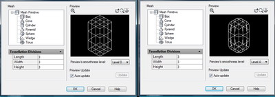
Figure 4: Side-by-side comparisons of the mesh settings in AutoCAD 2010. The left shows a preview of a mesh box primitive with a smoothness setting of zero. The preview on the right shows a smoothness setting of 4, the maximum setting.
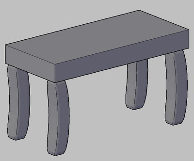
Figure 5: This is the same table as in Figure 3 except that the legs have been smoothed and "warped" using the new gizmos.
Crease (it isn't just for pants)
One of the downfalls of the smooth feature is that it smoothes the entire object. Sometimes you may want a specific area of your object to retain its edge. To do this, use the crease tool. Not that once you add a crease, you can remove it later.
The crease tool (and the remove crease tool) are found in the Mesh Modeling tab, located in the Mesh Panel. To use it, start the tool, pick your edges to crease, and then enter in a value setting. The value setting controls when the objects will retain their crease. You can select always, by level, none, or enter a numeric value. That numeric value will be the smoothness level in which the crease starts. You can crease vertices, edges, or faces. Each will create a crease in a different manner.
Mesh editing tools
There are two main mesh editing tools that will give you more control of your mesh objects. They are the Split Mesh Face command and the Extrude Face command. The split Mesh face allows you to redefine the edge of a face. You will pick two points that will create a new edge for the face, splitting it in to two new faces. Pick the first and last point where you want the face to be divided and then edit the new faces as you wish. The Extrude Face works just as the Extrude command did before. Select a face to extrude, and you can move it in or out as needed. Having more definition in your faces allows you to create more unique objects than ever before.
Conclusion
There are many new Freeform Modeling tools available to us in AutoCAD 2010. We can smooth objects, crease their edges, tessellate objects, and convert standard objects into mesh objects. These new mesh editing abilities gives AutoCAD users the chance to create more organic designs. It also allows users to design more freely. Who knew that the ability to be smooth could give you an edge?
.jpg)
Figure 6: I started with three primitive boxes (top right) and quickly used the tools discussed to create this plane.