TIPniques: AutoCAD 2011 Review Continued
Since AutoCAD 2011 was released, the Tipniques column in AUGI HotNews has been slowly reviewing the new features and new enhancements to the design program. I would say that we are at least halfway through. Maybe we can get all of the way through before the first service pack is released!
Parametric constraints
AutoCAD 2010 introduced Parametric Constraints. AutoCAD 2011 made them a bit better. Parametric Constraints are functions in AutoCAD that allow users to "program" their linework. They define and lock in certain design parameters into the model, or linework. One of the biggest (and best, in my opinion) enhancements to constraints in AutoCAD 2011 is the new Inferred Constraints. This function can be toggled on or off (like Osnaps or ortho). The toggle button is on the status bar on the bottom of the screen. Right click on it to bring up the constraint settings. With the Infer Constraints on, constraints are added to your linework as you draw them. It automatically applies coincident constraints for endpoints, midpoints, center points, nodes and insertion object snaps.
For example, with this on, when you snap to an object, the infer constraints will apply a coincident constraint to that point. The same goes with editing commands. If you move, copy, rotate, etc., the points you select will have a coincident constraint applied to them. If you place an object with the Nearest object snap, that point will have a coincident constraint applied to it. This is a very powerful design tool that now makes certain your design stay locked and in place.
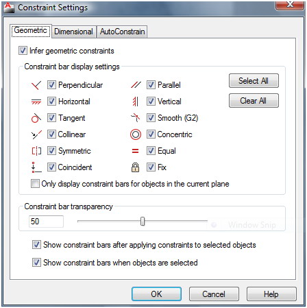
Figure 1: Right-click on the status bar to open the Constraint Settings dialog box. there you can toggle the Infer Constraints setting on or off.
Other Osnaps such as Tangent and Perpendicular will also apply coincident constraints to the objects used. Using the parallel osnap will automatically apply a parallel constraint to the objects. Inferred constraints also affect the way constraints are applied to the rectangle, fillet, and chamfer commands.
Constraining ellipses
More geometric constraints can now be applied to ellipses. The parallel, perpendicular, collinear, horizontal, and vertical constraints can now be applied. These constraints can be applied to the ellipses minor or major axis and to another object.
Constrain text
After AutoCAD 2010 gave us constraints, one of the biggest requests was for the ability to constrain text. Well, Autodesk listened and we can now constrain text by the parallel, perpendicular, collinear, horizontal, and vertical constraints. The insertion point of the text is the point constrained to the other object. If you have a roadway or subdivision plan set and you want to label the road, go ahead. Constrain the text with a parallel constraint with the road’s line work and it will stay parallel. Rotate the road and the text will follow.
AutoConstrain
AutoConstrain was already there in AutoCAD 2010, and it is different from Inferred Constraints. AutoConstrain adds coincident points and other geometric constraints based on the command used. AutoConstrain adds geometric constraints after the line work is done. It doesn't care how the linework was created. It looks for parallel lines and constrains them with the parallel constraint. It looks for perpendicular lines and constrains them as such. In fact, it goes through the user-defined list and applies the constraints you want, in a specific order. In 2011 the Equal Constraint was added. It is applied to lines of equal length or to arcs or circles of equal radius.
Constraint bars and icons
Constraint bars can now be show when you select objects, even if they have been hidden to clear up your screen. Once the selected objects are released, the temporary constraint bars are hidden again.
Constrain icons are different now. They visually indicate if a constraint is for an object or for a point. If it is for a point, there will be a dot in the icon. If it is for an object, no dot. Very simple, but it helps you to better understand the nature of the constraint. Since it is visual it also makes the identification process quicker.
Figure 2: The constraint icon on the left is for perpendicular lines. The icon on the right is for a coincident point.
Dimensional constraints
Geometric constraints define the geometry of your linework. Dimensional constraints define the length or lengths or your linework. The DIMCONSTRAIN command now has the convert associated dimensions to dimensional constraints as an option rather than this being the default behavior.
When you are creating a dimensional constraint, you can now click on an existing dimensional constraint to tell AutoCAD to enter the clicked constraints name into your new constraint. For example, if you dimensionally constrained one side of a parallelogram, as you dimensionally constrain a second side, pick the first constraint to make the second constraint equal to it. This way they will both have the same length. Or you could manually enter in the constraints name of the first side. If there are many constraints in your file it may be difficult to know which constrain is which. With this new feature you can just pick the ones you want to use.
Parameters manager
One issue with dimensional constraints is that a file can have a lot of them. Every time you add one the list gets longer. The more you use, the more there are to manage. There weren't any good tools in AutoCAD 2010 for managing them.
AutoCAD 2011 significantly improves this management process. It now has filter where you can create groups of parameters. For example, if you draw a series of gears, you can create a group of constraints called Gear 1 for the constraints in the first gear. Then you can create a list called Gear 2, and so on. Once a group is created, just drag the constraints into the group in which they belong. There is also a search box in the constraints manager. There you can search for a constraint or group. Make sure to name your constraints in a well-organized manner. This will help you work them more easily.
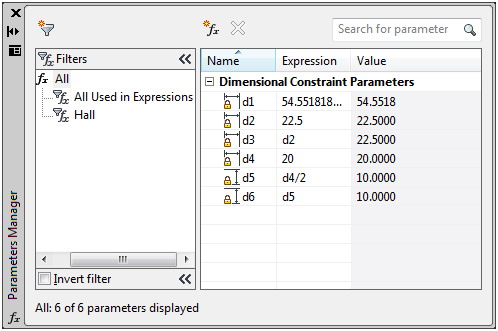
Figure 3: The Parameters Manager has new features that allow you to group your dimensional parameters into groups.
Conclusion
AutoCAD 2011 has added many new features to Parametric Constraints. These new features make it easier to manage your models constraints and make editing them more efficient. You can apply inferred constraints while you create your linework which will save you effort during your design process. You don't have to go back and apply constraints later, unless you want to.