TIPniques: AutoCAD 2010 New Features
In February HotNews, we took a look at the new parametrics that are in AutoCAD 2010. The March issue (excellently written by Melanie Perry) went through a long list of several of the new features given to us. Even though last month’s list of new features was long, there remain more to cover. Let's begin.
Customize the QAT
When a software interface goes through a "facelift," like AutoCAD 2009 did, we wonder if anything else can be changed in the next version of AutoCAD. Well, the interface in this release did change a bit, though not as drastically as the previous release. The Application Menu was heavily changed, the Ribbon was greatly improved, and the QAT (Quick Access Toolbar) was altered as well.
Autodesk gave us the QAT in 2009, but it was a little difficult to customize. You had to jump through several hoops in the CUI to do anything with it. In order to customize it in AutoCAD 2010, click the down arrow on the right side of the QAT and click the commands you want in it. If you don't want them in there anymore, do the same, but turn them off. And if you right-click any of the commands in the QAT, you get customization options. If there is a command you don't see in the list, click the MORE COMMANDS button to open the CUI window, find the command, and drag it into the QAT. Very easy.
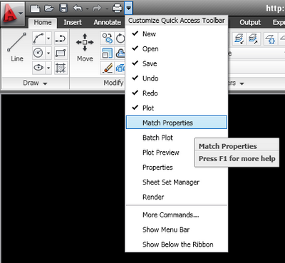
Figure 1: Click the arrow to open the QAT customization tools.
HELP! HELP! I need Help! Where’s the Help button?
Help can be found in the Menubar, if you have it turned on. In AutoCAD 2009 it was in the Application Menu, but that was overhauled. So where is it? You can always hit the F1 button, or type a ? on the command line. Now the HELP button is at the end of the Info Center. It is a circle with a question mark inside it. There is a pulldown feature providing several other help functions including Help, New Features Workshop (a must read), Additional Resources, CIP, and the "About..." info. So, when you need help or the New Features Workshop, go to the top right-hand corner of the screen.
More additions to Multileaders
Editing multileaders has gotten easier. Now you can grip edit the text just like mutlitext. If you want to expand or stretch the text box, grip edit it. The styles manager has been updated to provide more control of the leader connections. In the Leader Structure Tab, you can specify vertical attachment, not just horizontal. On the content tab, you can specify a scale when a block multileader type is selected. The block scale is now displayed in the properties manager. A new button on the content tab gives you direct access to the Text Style dialog box. That means that you can create or modify a text style without leaving the multileader style dialog box. One last thing, if you use the MLEADEREDIT command to add or subtract leaders from your multileader, you no longer have to select an option to either add or subtract leaders. It now adds leaders by default until you tell it to subtract.
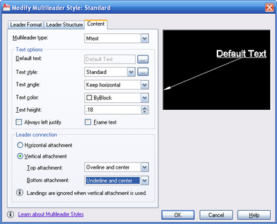
Figure 2: Multileader settings can now control the vertical attachment of the text to the leader.
More annotation enhancements
AutoCAD 2010 has several additions to its other annotation tools. The MTEXT editor now includes a default column mode of Dynamic with manual height. This enables you to make each column a different height. The spell checker has an undo button. Dimension styles have had settings added to them. In the Text Tab you can set it so the dimension text will be placed below the dimension line. There is a new view direction setting, making the text be displayed either from the left to the right or from the right to the left. Of course these new properties are also accessible in the properties manager.
The Primary and Alternate Units Tabs have a new Sub-Units feature, which provides new controls for leading zero suppression. It only works for metric units, but essentially you can set the dimensions to automatically switch to centimeters if the dimension measures less than a meter, or however you set it. For example, if the units are set to meter and you set the sub-units to 100 (and make the sub-unit suffix cm) then when the dimension measures below 1 unit (like .86 units) it will multiply the measured unit by the subunit and display the sub-unit suffix.
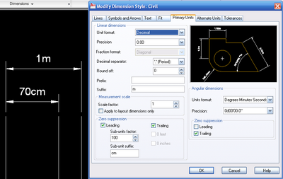
Figure 3: The new Sub-Units factor is used here to display a dimension of 0.7 meters as 70 centimeters.
External references
We all need to reference files (well, most of us anyway). Last month’s HotNews TIPniques article told us that AutoCAD 2010 can reference PDFs as underlays. Well, it can also Georeference files now. If both the host file and the referenced file have a geographic location, then the reference manager enables you to locate the attached file relative to the host drawing using the Geographic Data. The insert dialog box has the same feature. The Reference Tab in the ribbon has several tools in it. It has an attach tool, reference clip, fade, contrast, layer visibility, reference frames (on or off), and snap to underlay geometry. When you select a reference file in the drawing, a contextual tab is automatically displayed in the ribbon. You can display the reference frame for each type of reference. You can override these individual settings by using the FRAME system variable. You can also control the underlay osnap by reference type (use the DWFOSNAP, DGNOSNAP, or PDFOSNAP system variables). Again, you can override these settings with the variable UOSNAP.
If you open a file that has unresolved references, a new warning pops up. You will be given two options: either ignore the warning or click to update the file location. Selecting this option will open the External References Palette so you can repath the missing file. There is a box at the bottom of the warning window where you can click to always ignore this warning.
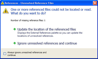
Figure 4: Here is the warning window when a file with unresolved reference files is opened.
Further enhancements
The Sheet Set Manager can now control whether a drawing, or sub-set of drawings, in a set is to be printed. To do this, right-click the Edit Subset and Sheet Publish settings, or the subset menu item. Sheet Set List Table functionality has been improved. You can now insert a table list of subset sheets.
Quick Views Layouts and Quick View Drawings now include a preview image of the model tab.
There is now an autocomplete feature when typing in file names.
In previous AutoCAD releases, no single object could be larger than 256MB. AutoCAD 2010 has increased the size of that limit to 4GB. There is an issue with this feature - it is not backwards compatible. In the options window, under the Open and Save Tab, there is a control option to turn this new feature off in the case you need to make sure you can back save your files. When turned off, AutoCAD 2010 will apply the old limit to objects.
AutoCAD 2010 has 3D printing functionality. This ability allows you to print your models to a 3D plotter. The utility will walk you through the steps, helping you to prepare your model. It will then send it to the proper vendor. When your file is created for sending, you will automatically be sent to an Autodesk website that you help you select the 3D Printing Vendor you want to use. Use the command 3DPRINT to start this feature.
Content Search has been renamed to Autodesk Seek and is more efficient. You can start it right from AutoCAD. This feature helps you locate product specific specifications and download a file into your AutoCAD drawing. Type SEEK on the command line to start the feature.
Conclusion
AutoCAD 2010 has added many new features. Some of these features have been requested over and over again by many users. AutoCAD 2010 also incorporates many new features that are similar to the vertical applications produced by Autodesk such as parametric constraints. The Ribbon has been improved upon, PDF abilities have been added, and 3D printing functionality is now there. Enjoy!
We aren't quite finished yet. There is one major aspect to AutoCAD 2010 that we haven't discussed. Those features are in AutoCAD’s new 3D features and free-form design abilities. AutoCAD 2010 can handle meshes now and has improved 3D operations. The free-form design features can create meshes, creases, and smooth 3d solids, allowing for more organic models to be created. Yes, organic modeling has finally come to AutoCAD!
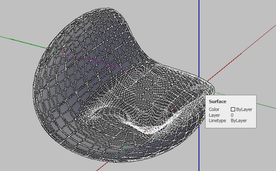
Figure 5: This free-form model, made of two rectangle box objects, was turned into a mesh surface with AutoCAD 2010 software’s new free form modeling tools.
We may have missed a few items here or there and I know we didn’t get into all of the new features in as much detail as many would like, but we have all year to talk about them. That is, until AutoCAD 2011 comes out!
.gif)
(Discuss this Article! in the HotNews Discussion Forums.)