The Civil Side: Managing Large Surface Data
In today’s land surveying and civil engineering world we find that with the advancement of technology we are able to collect larger and more accurate amounts of data from the field in a shorter timeframe. This is great news for our engineering designs, but having a lot of data can be problematic when it comes to importing it into design software. How much data is too much? How do we pare down the data so that it is usable in AutoCAD Civil 3D without compromising its integrity? Can we really use LIDAR data in Civil 3D? I will be explaining multiple ways that you can pare down your data so that it can be used in Civil 3D and still output an extremely accurate surface model for engineering design.
Previous versions of Civil 3D (prior to 2009) supported only a surface model with roughly one million TIN points. Once your surface grew to be above this level the recommendation was to break up the surface into multiple drawings. With Civil 3D 2009, once your surface grows to 2.5 million TIN points an external MMS (Memory Map Surface) file will be created to handle the large dataset. We will take a look at various ways to limit the size of your surface data using:
- Custom point file creation (for import)
- Data-Clip Boundary
- Simplify Surface Command
- Weeding Contour Data
How-to create a custom point file to limit the amount of point data that will be imported
-
Points --> Import/Export Points --> Import Points, see below:
.jpg)
-
Create a new point file format. In order to do this it is best to copy an already existing point file format such as PNEZD (comma delimited), as shown below.
.jpg)
-
Within your new point file format, choose to sample every 5 points. Keep in mind that this is a simple weeding of your points file; it will select every fifth point and throw out the rest, as shown below.
.jpg)
After you have created your new point file format you can import your ASCII file and it will weed points based on your "Sample every" value. If you are working with extremely large Lidar data, consider increasing your "Sample every" values.
How to create a data-clip boundary for your surface to limit the amount of data that will be used to build your surface model
-
Create a new Surface; right-click on Surfaces in your Prospector tab of your Toolspace --> Create Surface, as shown below.
.jpg)
-
Once you have created the shell for your surface, you can create a "Data-Clip boundary." NOTE: Data Clip Boundaries must be created prior to importing your surface data to ensure that any information that extends beyond the limits of your boundary is NOT imported into your drawing. Expand your Existing Ground surface --> Expand Definition --> right-click on Boundaries --> Add, as shown below.
.jpg)
NOTE: It works best to have an image of the area where your surface is to reside. You can then use this image as a guide to draw in your Limit of Work boundary. Your boundary polyline must be drawn prior to definition.
- Import your surface data, whether it consists of points, contours, breaklines, or other entities. Notice that the only data that was imported is within the limits of your previously defined boundary.
How to use the Simplify Surface command to weed out unnecessary data without compromising the integrity of your model
-
After your surface has been created, expand you Existing Ground surface --> Expand Definition --> right-click on Edits --> Simplify Surface, as shown below.
.jpg)
- Select Point Removal for the "Simplification Method."
-
Skip the "Region Options" menu.
.jpg)
NOTE: When reducing the number of TIN points for your surface, AutoCAD Civil 3D will take into account two settings. The first is the percentage of points to remove and the second is the maximum elevation change. Be assured that the program will only remove points that do not affect the maximum elevation change, thus maintaining the surface integrity.
-
Hit the Apply button and notice the "Total points removed."
You can continue to hit the apply button until the number of points removed is down to zero. Keep in mind that when you hit the Finish button, Civil 3D will run the simplify surface command one last time. You are able to find these multiple point removal iterations in your Surface Properties --> Definition Tab, as shown below.
.jpg)
How to use weed out vertices along contour data
- Create a new surface, give it a name, description, and choose a style
-
Expand your new surface --> Expand definition --> right-click on Contours, as shown below.
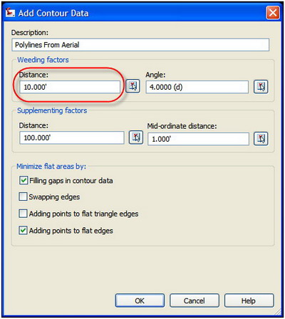
NOTE: When setting the "Weeding factor," keep in mind that the larger the value for the Distance, the fewer the number of vertices that will be removed. If your value is set to 10, as shown in the image above, this will remove any vertices that are less than 10 feet (or meters, depending on your drawing units) apart.
In conclusion, there are many ways to limit your surface size and weed out unnecessary data while still maintaining your surface's integrity. Only you, the engineer or surveyor, can determine what data needs to be used in order to build an accurate existing surface model.