The Civil Side: Dust Off That Civil 3D 2009 Box!
Do you have a copy of AutoCAD Civil 3D 2009 just sitting on the shelf at the office "collecting dust?" Or maybe you have a copy installed but have been too afraid to open it because its interface is drastically different that your current design software. This lesson is intended for organizations that have not yet cracked open the box of Civil 3D software. During this "How-To" guide, I will cover many Civil 3D capabilities that can be used immediately with very little or NO training investment.
- Navigating through the Civil 3D Interface (5 min)
- Creating, Displaying, and Editing Surfaces (10 min)
- Surface Volume Calculations (5 min)
- Alignment Creating and Editing (5 min)
- Exiting Ground Profile Generation (5 min)
Navigating through the Civil 3D Interface (5 min)
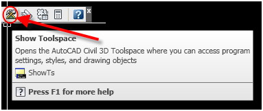
Upon opening up Civil 3D 2009, make sure that you have the Toolspace open for ease of navigation in the program. There are three ways to ensure that this dialog box is open.
- General pull-down menu --> Toolspace
- Type "showTS" into the command line
-
On the Civil 3D Standard toolbar (see image below).
Once you have the toolspace open, you can treat it like any other palette inside of AutoCAD. It can be floating, docked, or set to Auto-hide.
A brief explanation of the tabs on the Toolspace: When it initially comes up, it will have two tabs - Prospector and Settings - but you can also add a Survey and Toolbox tab. The definitions of the tabs on your Toolspace are as follows:
Prospector Tab: Use the Prospector tree to manage and access drawing and project objects.
Settings Tab: You can use the Settings tab to manage styles for AutoCAD Civil 3D objects and to control settings for drawings and commands.
Survey Tab: You can use the Survey tab to manage survey user and system settings as well as survey data.
Toolbox Tab: You can use the Toolbox tab to access the Reports Manager and to add custom tools.
When using Civil 3D out of the box there is no database and external folder system, as Land Desktop had. By default, everything you have is stored directly in your .dwg file. All of your intelligent objects such as Points, Surfaces, Alignments, Parcels, Profiles, and Pipes are stored directly in your drawing file and can be accessed by right-clicking the collection in the Prospector tab OR selecting the object in your drawing and right-clicking on that object. Civil 3D is heavily "right-click based" and light on toolbars and pull-down menus. Civil 3D 2009 has a total of only seven toolbars. By contrast, Land Desktop had upwards of 50 available toolbars.
With regard to the Settings tab, all of your Object, Label, and Table styles can be accessed through the Settings tab. This information comes from your .dwt or drawing template file. ALL standards inside of AutoCAD and Civil 3D can be stored in a template file. In Land Desktop, the template file housed all of the AutoCAD standards and the Prototype house all of the Civil Engineering specific standardization.
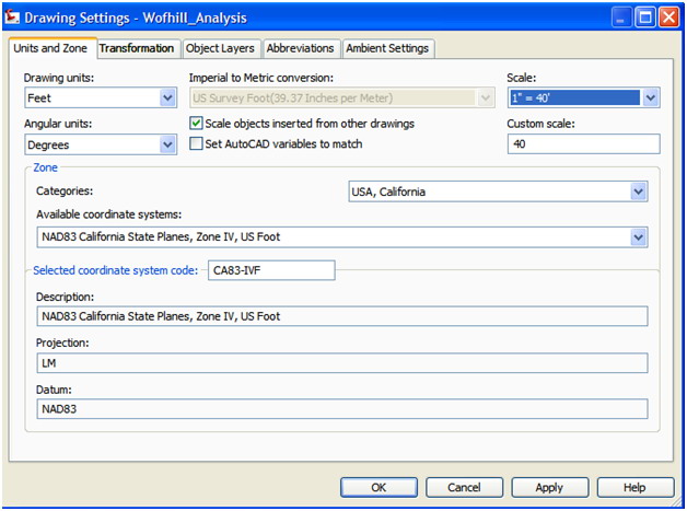
In order to set up your drawing settings (meaning the drawing scale, coordinate zone, object layers, units, and precision) you need to:
- Select your Settings Tab on your Toolspace (directly below the Prospector Tab).
-
Right-click and select Edit Drawing Settings (see image below).
.jpg)
Once you have set up your drawing settings you are ready to begin to navigate through Civil 3D. One thing that needs to be understood is that Civil 3D works in a hierarchy from the Drawing Settings, which is at the top of the Settings Tab, to the individual objects down below. If you set up your Ambient Settings within your drawing settings to have a specific Unit, Precision, Rounding, and Sign at the drawing level, these settings will propagate to the individual Civil 3D Objects down below. One thing to note is that these drawing settings CAN be overwritten below in the hierarchy for the individual objects. Please see below for how to determine if a setting has been overwritten.
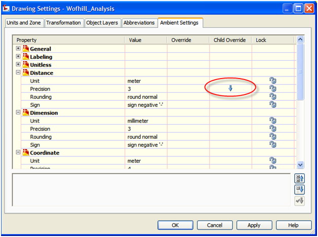
Keep in mind that if an entity is overwritten below in the hierarchy, you will receive the blue arrow in the Child Override column of your Ambient Settings. Unfortunately, there is no way to locate where this override is taking place, but you can select the blue arrow in the Child Override column and omit this override altogether.
Now that your drawing settings are in order, I will assist you in navigating through the drawing once you have Civil 3D objects in it. There are a couple of ways to manage and edit your drawing objects such as Points, Surfaces, Alignments, Profiles, Sections, Parcels, Grading Objects, Corridors, and Pipe Networks.
-
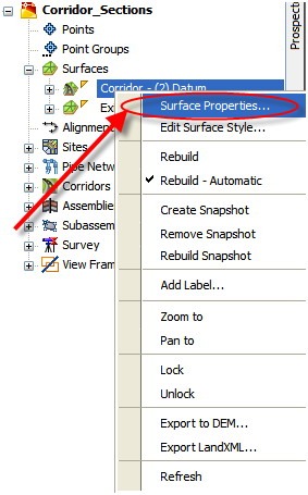
The first way is as follows. On the Prospector Tab of your Toolspace, right-click and select the "object" properties (in the image below, I am working with a Surface, so you select Surface Properties)
- The second way is to simply select the object in your drawing window --> right-click and select properties directly.
Creating, Displaying, and Editing Surfaces (10 min)
NOTE: When using Civil 3D Out of the box, please use the _AutoCAD Civil 3D (Imperial) NCS Extended.dwt to begin your drawings. This template, which ships and installs with the products, contains the most Civil 3D Object, Label, and Table styles. As you become well-versed in the software and start producing and printing plans, you will need to create a custom template file with your company's standards. This is a great place to start.
Whether you are creating an existing ground surface from a ASCII Point file, Point Group, Aerial Contour Data, or Breakine Data, I can give you a quick way to turn your existing 3D data into a Civil 3D Surface Model. We are going to start with using a point file to create a surface. Please note that when creating a Surface model from a point file, the actual COGO points DO NOT get inserted into your drawing file. Your Civil 3D Surface will look to an external location to read the point file, so if you move your drawing or move your point file you will have to re-path this information in order to maintain the link between your surface and its points. The benefit of using this method to create surface is that it will help you maintain a smaller drawing file size. Here we go.
- In your Toolspace, select your Surfaces collection --> right-click and select Create Surface from the top of the list.
-
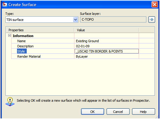
In your Create Surface Dialog box you can give your surface a name, description, and style (to show how it will be displayed once you add your data to it), as shown below.
-
Once the "shell" for your surface has been created, you can now add your data to build your model. Expand your newly created Existing Ground Surface --> Expand Definition --> Right-click on the Point Files collection and select Add, as shown below:
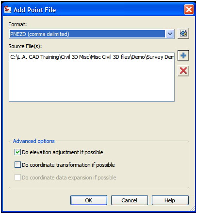
- Select the point format --> Hit the + sign and browse to the point file location. NOTE: You can select more than one point file at a time using the ctrl and/or shift keys.
Building a Surface using Aerial Contour Data
- Please follow the above steps 1 and 2 to create a new surface shell.
-
Once the shell for your surface has been created, you can now add the data to build your model. Expand your newly created Existing Ground Surface --> Expand Definition --> Right-click on the Contour collection and select Add, as shown below.
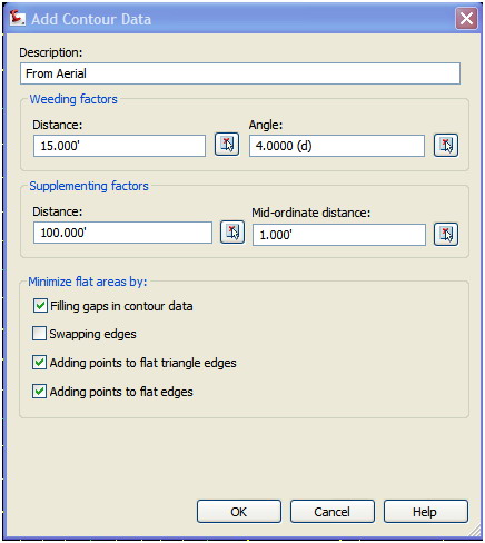
NOTE: In the "Add Contour Data" dialog box, you have the option to use weeding or supplementing factors to your data. This will weed out data if there appears to be an excess or add data to areas where this is not enough. The weeding factor is set to 15’ by default; this means that it will remove any vertices that are less than 15’ apart from one another. There are also tools to "Minimize flat areas by:" - commands include the following.
Filling Gaps In Contour Data - Specifies that small gaps in contours should be filled in.
Swapping Edges - Specifies that a non-contour common edge shared between a flat triangle and a non-flat triangle should be swapped.
Adding Points To Flat Triangle Edges - Specifies that a new point should be added at the midpoint of an edge shared between a flat triangle and a non-flat triangle.
Adding Points To Flat Edges - Specifies that a new point should be added to edges that bridge two same-elevation data contours and are not in flat triangles.
Basic TIN Surface Editing Techniques
Once you have your surface model built, you must first display it as a TIN and make sure that you have the Points displayed in order to perform the next steps. To ensure that this is set up correctly you can select the surface --> Right-click and select Edit Surface Style --> In your Surface Style dialog box, select the Display tab and make sure that Points, Triangles, and Border are set to Visible for both Plan and Model.
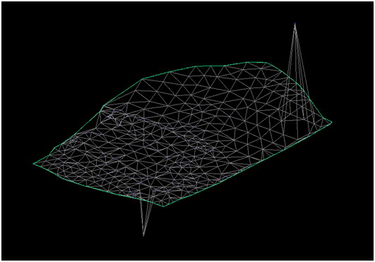
Our first editing technique will enable us to edit the TIN surface if there is a blown elevation or spike. See below.
-
Expand your Existing Ground Surface --> Expand Definition --> Right-click on Edits --> Select Modify Point. See below.
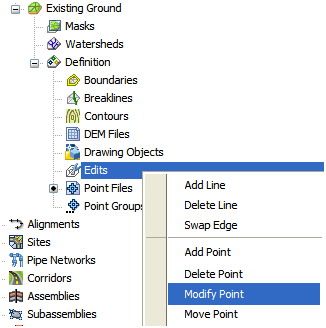
- Select the erroneous point --> Hit enter --> Type in the correct elevation value --> Hit Enter and watch your surface automatically adjust.
The next editing technique is to delete TIN lines when your surface model is interpolating information in an area where you are lacking 3D data.
-
Expand your Existing Ground Surface --> Expand Definition --> Right-click on Edits --> Select Delete. Hit C on your keyboard in order to use a crossing window to delete the necessary lines, as shown below.
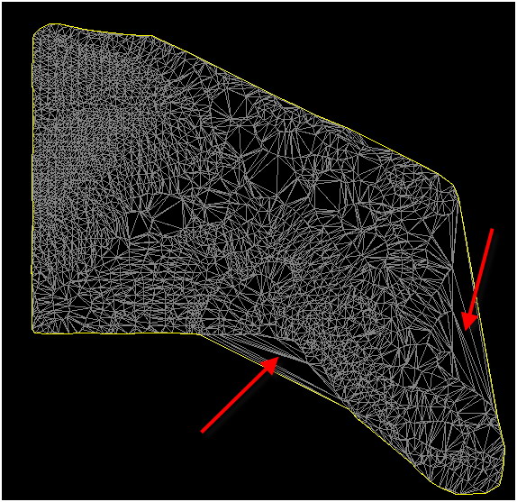
- As you delete a group of lines you will need to Hit C to invoke the crossing window command again once you hit the enter key if you will see your border automatically adjust to fit your new surface model.
Surface Volume Calculations (5 min)
Here are two quick volume calculation methods. One is a quick calculation that will allow you to compare multiple design alternatives and then once you have made your final design decision, we can explore how to create a volume surface that can be used for further analysis.
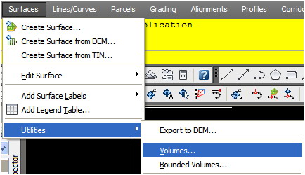
Surface Volume Tabular Method
-
Go to your Surfaces pull-down menu --> Utilities --> Volumes, see below.
-
In the Composite Volumes panorama window you are able to add multiple entries into the table to compare multiple design alternatives, see below:
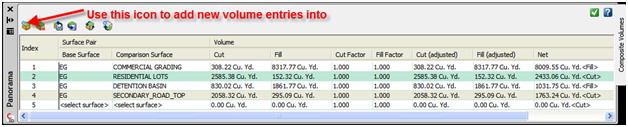
NOTE: In the volumes table you do NOT have the ability to calculate Grid Volumes; you can ONLY calculate Composite Volumes. If you need to create a Grid Volume, use the process listed below.
The next volume calculation method is to create a volume surface. This will allow you to create a cut/fill analysis or any other color banding that you wish to create. Using this method you will be creating a model to display your volume information as opposed to the previous method that simply supplied you with calculations in a grid view.
-
Create a new surface by right-clicking on Surfaces in your Prospector tab of your toolspace. (Refer to surface creating techniques discussed previously in this guide.) See below.
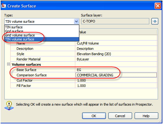
- Make sure to select either Grid or TIN (Composite) volume surface.
- Select your Existing Surface for your Base Surface and your design for Comparison Surface.
NOTE: You can adjust your Cut and Fill Factors to account for shrinkage or expansion.
Alignment Creating and Editing (5 min) There are two methods to create horizontal alignment geometry. The easiest way, which we will explore in more depth, is to turn an existing AutoCAD Polyline into an Alignment Object. The more advanced method is to create your horizontal geometry "by layout."
-
Go to your Alignments pull-down menu --> Create Alignment from Polyline. (You must have your polyline in your drawing before beginning this command.)
NOTE: It does NOT matter in which direction the polyline was originally drawn - you simply select which end to begin your alignment stationing.
-
Select your polyline that you wish to turn into an alignment object, as shown below.
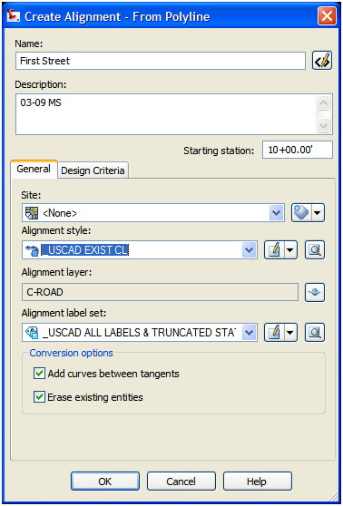
NOTE: When creating an alignment object from an existing polyline, you have two conversion options at the bottom of the Create Alignment dialog box. You can choose to delete your original linework and add curves between tangent lines. We will next explore how to edit your alignment geometry in both graphical and tabular form to cycle through design alternatives.
In order to further edit your alignment location, tangent sections, curve data, and PI information, you can select the alignment and notice you get a variety of grips for graphical editing.
 AT END OF LINE OR CURVE - Move an unconstrained pass-through point on a line or curve. On a line, moving this grip affects the length and angle of the line. On a curve, moving this grip does not affect the radius of the curve to which it belongs, but it may affect the radius of another attached entity.
 AT CENTER OF LINE - Move an entire line. Moving this grip only affects the line location.
 AT END OF LINE OR CURVE - Change the constrained length of a line or curve. This grip appears on lines and curves that have a directly editable length and is aligned with the vector at the end of the line or curve. Moving this grip does not affect the radius of a curve or angle of a line.
 AT CURVE CENTER POINT - Change the center point of a circle. Moving a center point changes only the center point.
 AT PASS-THROUGH POINT - Change the pass-through point and radius of a curve or circle. Moving a pass-through point affects the radius of the curve.
 AT POINT OF INTERSECTION - Change where two tangent points meet. This grip is oriented up with the top point toward the Y axis of the world coordinate system.
 AT PASS-THROUGH POINT - Change the radius or through point of the curve. The triangle grip appears on curves that have a directly editable radius and is oriented in and constrained to the direction of the change. The circle grip changes the pass-through point and radius of the curve.
Exiting Ground Profile Generation (5 min)
Creating an Existing Ground Profile in Civil 3D is not only an extremely easy task as profile generation has a wizard to walk you through the steps with ease, but the fact that your profiles in Civil 3D are dynamic with your surface and horizontal geometry make your design tasks that much more fluid and less erroneous. Before creating a profile object inside of Civil 3D, you must first have a surface model for your 3D data and an alignment object for your horizontal data. We have explained how you create these necessary objects above.
-
Go to your Profiles pull-down menu --> Create from Surface, select your Alignment and Surface and hit the Add button and hit the Draw in profile view to see your existing ground profile in a grid.

-
This will then take you into the Profile View Wizard that will walk you through the process of creating a profile view. You will accept the default settings for your first attempt and ease of use. See below.
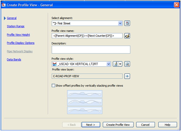
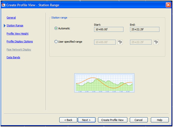
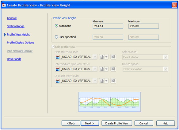
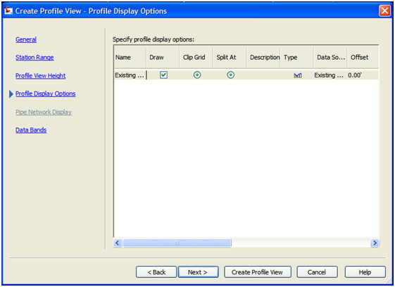
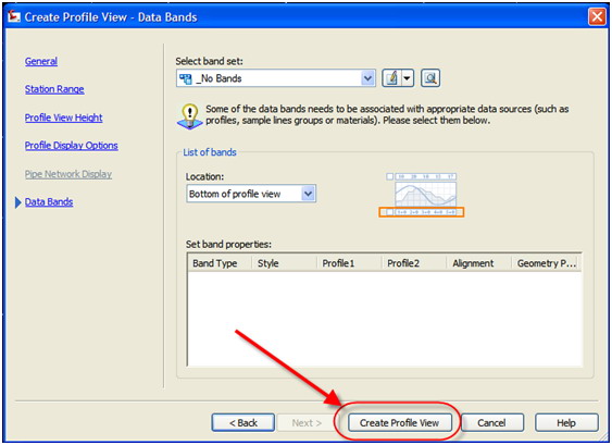
- Hit the Create Profile View button and place your profile somewhere in your drawing. Not to worry... if the location of your profile needs to change, just use the grip or AutoCAD move command to relocate it at anytime without repercussions. Also, if your horizontal alignment or existing ground surface happen to change, your profile will be dynamically updated.
This concludes my How-To Guide for dusting off your box of Civil 3D. If you have questions, please do not hesitate to contact me at melanie.santer@uscad.com.