Stressed! Autodesk Inventor Simulation FAQ
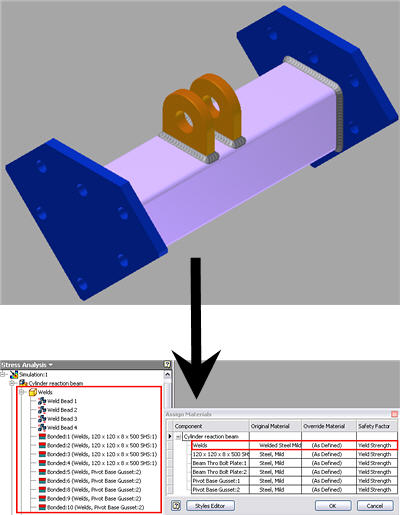
Q: Can I perform stress analysis on a weldment assembly?
A: Yes. Open the weldment assembly and then select Stress Analysis from the Environments tab. Automatic Contacts will create bonded contacts between the welds and components, by default. In addition, the different material properties of the components and welds will also be retained within the Stress Analysis environment. Beware: High stress results may occur at the welds due to sliver elements such as highly distorted elements.
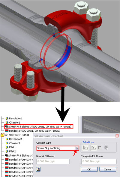
Q: Can I take account of components that have initial interference within stress analysis?
A: Yes. Within the stress-analysis environment, right-click the automatic bonded contacts for the components in question and select edit contacts. Select Shrink Fit/No sliding (or Shrink Fit/Sliding) from the contacts list. This will create pre-stressing in the component as a result of initial interference within components. Beware: In reality components will have frictional properties at contacts which are not taken into account.
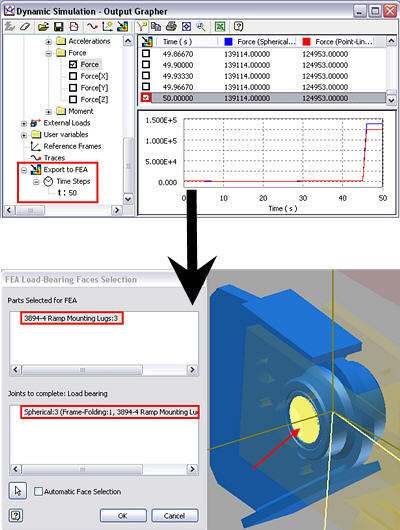
Q: Can I make use of reaction loads, available from dynamic simulation, in the stress analysis environment?
A: Yes. Select the time at which you want the reaction load to be transferred. Then select the component that needs to be analyzed and then select the faces where load is going to applied. Now create a new stress analysis and select motion load analysis option. The loads will be automatically applied to the component.
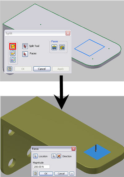
Q: Can I apply a load on a specific area and shape of a face?
A: Yes, you can apply a load, or constraint, on a specific area of a component face. In order to achieve this you initially have to draw the desired shape on the face and then, using the split feature, split the face within the part environment. This split face will then be available within the Stress Analysis on which to apply the load.
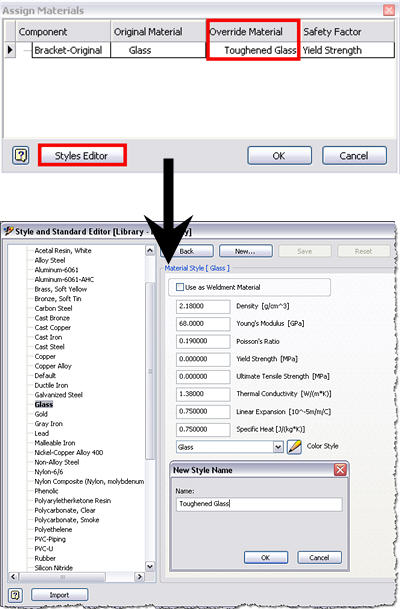
Q: Can I create new materials in Stress Analysis environment?
A: Yes, you can create new materials within Stress Analysis environment. Select Styles Editor from within the Assign materials dialogue box to create a new material. Once this new material has been created, it will be available from the override materials list which can then be selected to be applied to the component.
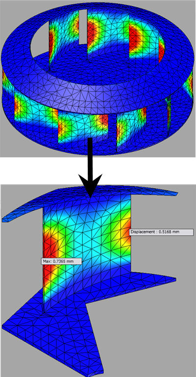
Q: Can I perform stress analysis on Quarter, Half, and/or Cyclic Symmetry models instead of the full model?
A: Yes, you can. In order to achieve this you initially have to split the part into a quarter, half, or single blade (cyclic symmetry) as in the example below using split feature to split the part within the part environment. Then you apply frictional constraints on all the faces created as a result of using the split feature. Then apply any other loads and constraints as normal.
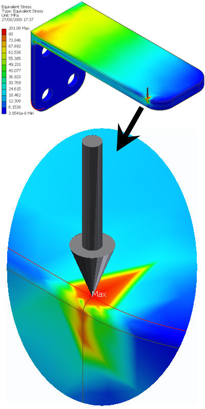
Q: Can I avoid creating high localized stress result as it affects convergence of results?
A: Yes. Avoid applying loads on edges or points as this is will create high stresses (this also applies to restraints). This occurs because Autodesk Inventor Simulation treats all components as rigid and can only perform linear analysis.
Based on this formula Stress = Force/Area stress will be very large (infinite) if the area is very small. An area of a point and edge is very small and this is why it is advisable to avoid applying constraints and forces on points or edges as it will result in very high stresses, also referred to as Stress Singularities.