Introduction to the Construction Environment
.jpg)
Quite often we are called upon to import geometry from other 3D CAD systems. Nearly just as often, the imported geometry will have problems that prevent it from being healed into a solid model, which is normally our primary goal. This article will assume that you have utilized the File Open >> Options correctly when selecting a file to import.
In the example below, I have imported what amounts to a pure surface model. While I have set the healing and stitching options in the import step, the result is still a surface model. At this stage, I can only assume that there are probably some surfaces missing, or there are surfaces that have gaps between them.
After importing this file, utilizing the import options correctly, I end up with the result shown directly below:
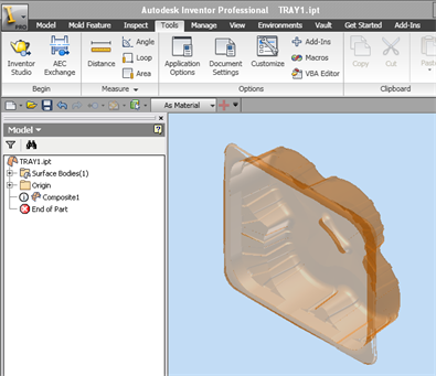
You will notice that in the image above, there is a circled "i" icon next to a feature called Composite1. The name and the icon indicate that the feature is a surface composite and that it has errors in the feature. When this is observed within a file, then your only recourse will be to copy the composite to the Construction Environment. Simply right-click on the composite and select Copy to Construction.
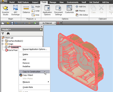
There are now two instances of this composite existing within the current part file. This is an area where a number of users become confused as to what to do next. The two instances are currently overlaid on top of one another, making it difficult to work with the geometry.
Let's make it easy. Once the composite has been copied to the construction environment, you may then delete the original composite, as shown below. Simply right-click on the bottommost instance located in the Model Environment and select Delete.
.png)
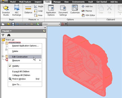
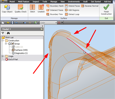
Now that the original instance has been deleted, we are ready to edit the composite in the Construction Environment. Right-click on the Construction folder and select Edit Construction. You will see that when you select the Construction folder, the part instance will be highlighted, as shown below.
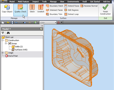
In this example you will see that there are two solids and 435 surfaces, which together compose this model. A Composite is also known as a collection of surfaces stitched together into one or more surface quilts. Further analyzing this model by changing the visibility of the surfaces, I find that the two solids are very small objects along one upper edge of the tray.
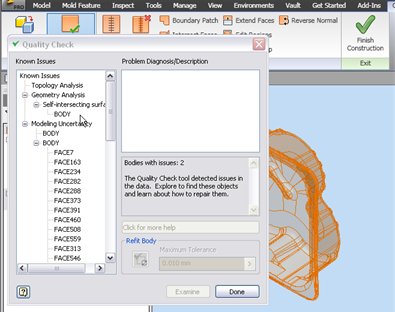
The next step in analyzing the model will be to perform a quality check. Pick on the Quality Check icon, and Crossing Window (right to left) all of the objects in the graphic screen. Once all of the objects have been selected, pick Examine to perform the Quality Check.
The results of performing the Quality Check on this model are shown below. You will note that the dialog shows two bodies with issues. The first issue is a body with self-intersecting surfaces that must be repaired. The second issue describes a Modeling Uncertainty containing numerous faces that may have errors. These errors could be gaps between surfaces, quite often being missing surfaces.
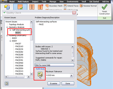
Let's try to correct the errors by selecting the first error message in the list, which in this file would be the self-intersecting surfaces. Select the body in the dialog box and pick Refit Body.
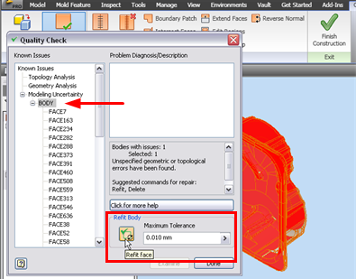
Autodesk Inventor will now attempt to refit this body using the Maximum Tolerance indicated. If this repairs that specific body, then it will disappear from the list as shown below. Once the first body is repaired, and is removed from the list, we can then attempt to do the same on the second body.
Note that the refit on the second body fails. This is more than likely due to missing or corrupt surfaces. In this model, the default maximum tolerance is listed as 0.010 mm. As a test, I will reset the maximum tolerance to 10x or o.10 mm, and attempt to refit the body once again. This attempt also fails.
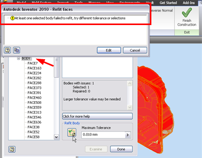
A third attempt at 1.0 mm also fails, thus confirming my fears that there are missing surfaces in this model, as shown in the enlarged view below. Further analysis of this model shows that an excessive number of surfaces are missing. While this model could be repaired, given enough time, by selecting the Surfaces group in the construction environment, then right-clicking and selecting the Copy Object command which would then copy the surface folder to the Modeling Environment.
This approach to recreating the missing surfaces in the modeling environment, will more than likely be extremely time-consuming. Before undertaking such a project, try obtaining a cleaner model from the original source. In Autodesk Inventor 2010, a better approach might be to request the original model file rather than a translation.
Next month's column will continue with repairing a surface model utilizing the construction and modeling environments. Until then, you may explore other aspects of the Construction Environment in Inventor Help