AutoCAD Architecture: Structural Styles, Part 3
Welcome back! In the earlier lessons in my series on creating structural member styles using custom member shape definitions, we learned the concepts of creating a basic structural member style using a single shape. Now we'll proceed with more examples. This time, we will create a structural member style (hereafter referred to as SMS) that will use two shapes. As an example, we will use a composite column.
Below is a sketch showing the cross section of a composite column with encased H-Steel profile.
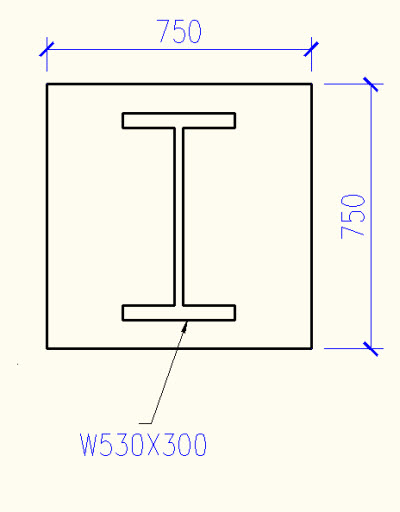
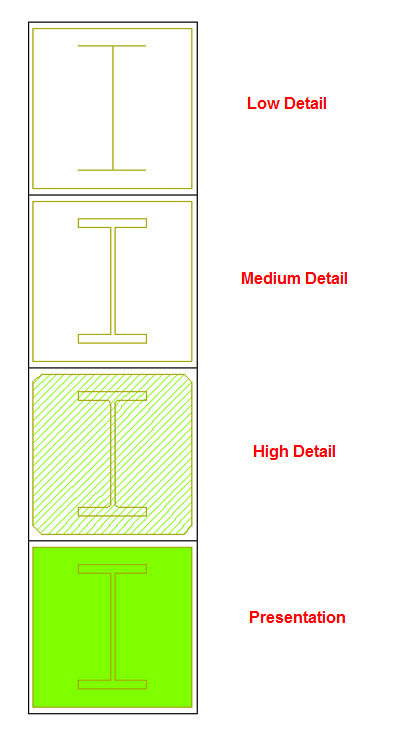
You will notice that there are two shapes required to create the SMS we want. One is the 750x750 square profile and the other one is the W530x300 wide flange shape. If you decide to draw these shapes using polylines, you will have to draw two, three, or more versions of the same sketch depending upon the type of details you will be plotting. For example, the above sketch is drawn for a medium detail representation of the column. The same sketch drawn to show a high detail would look like the one below.
.jpg)
The difference you see is not only the hatch details popping up, but also notice the fillets appearing where the flange and web meet. And maybe the low detail version of the same sketch would be as shown below.
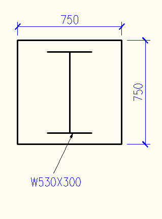
In addition to the low-, medium-, and high-detail representation of the composite column, you might even need one more for a presentation plan. That, we will do later.
Either you can draw the above shapes using polylines and keep them ready before you could create an SMS, or you can try the Structural member Catalog/Structural member Wizard. you might think that these two methods are used to create an SMS and not the structural member shape, but they do! So rather than creating polylines, let's try to save some time using the Wizard.
- Open a new drawing based on a metric template.
-
Click Manage tab --> Style & Display panel --> Structural member Wizard (command line: membershapeinsert).
You will see the 'Structural member Wizard' dialog open and you will be in step one of three.
- Under Concrete, select Rectangular Column and then click Next.
- Click the values to edit them. Type '750' for both the section width and depth.
- For the style name, enter 'C_750x750'
- Click 'Finish'.
What we have done is create an SMS. But what is more interesting is the structural member shape that got created in the background. To confirm this:
- Click Manage tab --> Style & Display panel -->Member Shape (command line: membershapeinsert).
In the Insert Member Shapes dialog, you will see the shape 'C_750x750' listed. Just to remind you again, what you see here is the name of the shape, which is, by default, named the same as the structural member. Click cancel to return to the drawing.
Alternatively, you can also issue the 'membershape' command to ensure that the shape C_750x750 was defined. Also note that, by default, shapes are defined for low, medium, and high details. But you are free to change the shapes representing a particular detail later.
Similarly, you can define the wide flange H-Shape, provided you know all the dimensions. For example, if you use the structural member wizard to define the H-shape, you will have to enter all dimensions as shown in the figure below (dimensions shown are not for 'W500x300').
.jpg)
So let's try to do this with the help of the structural member catalog.
- Click Manage tab --> Style & Display panel --> Structural Member Catalog.
In the left pane, browse to:
-
Metric - Steel - AISC- I-Shaped -Wide Flanges-W5nn,Wide Flanges
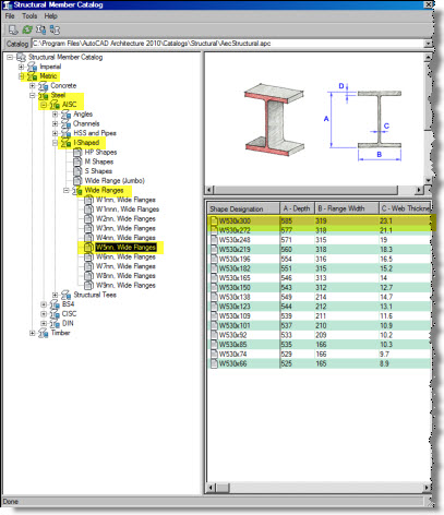
- In the right pane, select W500x300, right-click and choose Generate Member Style...
- In the pop-up, accept the default name and click OK.
- Close the Structural member Catalog.
What we did now is to create an SMS named W530x300. But what is more interesting is the shape called in W530x300 that got created in the background.
Use the 'membershape' command to see the shape listed. You will also notice that shapes are created for the three low, medium, and high details.
Now, we can go ahead and create the SMS.
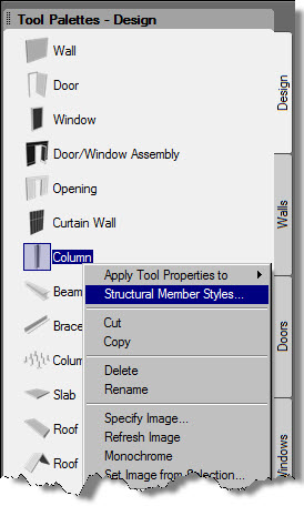
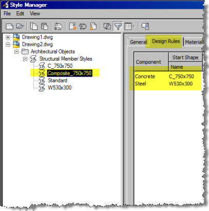
- In the Design Tool Palette, right-click on the Column tool and select Structural member Styles.
- In the Style Manager dialog, in the left pane, right-click Structural member Styles and select New.
- Type 'Composite_750x750' for the name.
- In the right pane, click the Design Rules tab
- Under Component, click Unnamed and type Concrete for the name.
- Under start shape, select 'C_750x750' for the shape.
- Click the Add button to add one more component.
- Name this 'Steel' and select 'W530x300' for the shape.
- Click OK to close the style manager.
To see the SMS you just created, add a column of this style into the drawing. Do remember to check the display of the SMS in low-, medium-, and high-detail display configuration.
In this lesson, we took a step forward and learned to create an SMS that uses more than one component. In the next lesson, we will see how to change the shape of the member along its length/height. See you all next month.