AutoCAD Architecture: Creating Structural Styles
Welcome back! We have spent the last few months taking a look at all the new features and enhancements in ACA 2010. This month, we return to learn more about AEC objects.
In the earlier articles, we discussed the three methods used to create structural member styles.
-
Browse the Structural Member Catalog to find the SM you want. The catalog can be accessed through the Format menu and then " Structural Members – Catalog."
From the ribbon: Manage tab ->Style & Display panel-> Structural Member Catalog.
Command: AecsMemberCatalog
-
Using the Structural Member Style Wizard. Nothing can be easier than this three-step solution to create the SM you want.
From the ribbon: Manage tab -> Style & Display panel -> Structural Member Wizard.
Command: AecsMemberStyleWizard
-
Using Member Shapes and Member Styles.
If you didn't find the required structural member in the Structural Member Catalog or if the required shape is not available in the Structural Member Style Wizard, you can create your own member shape/shapes (closed polyline) and then create a structural member style, which uses this shape as the cross section.
We have already discussed the first two methods in the earlier lessons. Now, we will take a look at the third method.
Open a new file based on any of the AEC Model metric templates. In this example, I'm using the Aec Model (Metric - UK Ctb).dwt. This is to load some predefined display configurations into the drawing. If you do not use a template, display configurations will not be loaded. Later, as AutoCAD Architecture is implemented at your company, the CADD manger would provide you with the company standard template, which will load the necessary display configurations as designed.
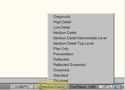
Check out the figure below to see the display configurations loaded.

If you ever wondered what display configurations are, don't worry. We will discuss display configurations in upcoming lessons. Different display configurations can be assigned to different vports in the paper space layouts. Display configuration is the power of AutoCAD Architecture. It helps the architect to view and plot drawings the way he or she wants to in different stages of the design without spending any time to redraft.
In this exercise, we get introduced to the basics of display configuration.
-
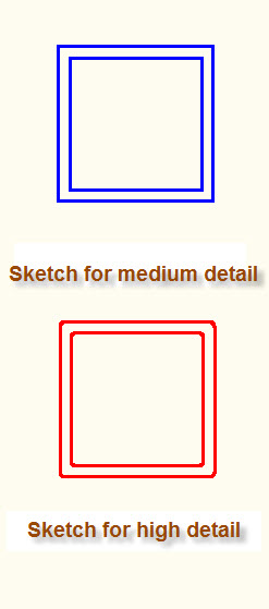
Create the following sketches representing hollow structural sections. Use closed polylines. Assume your own dimensions. Also notice the corners filleted in the second sketch, which is a slightly more detailed way of representing the hollow section where the earlier one offers less detail.
In the earlier articles, we saw examples of profile definitions for various objects such as doors, railings, and so on. What we are going to do now is similar to defining profiles, but we call this "defining a shape for a member" and we will use a different command.
- Command: membershape
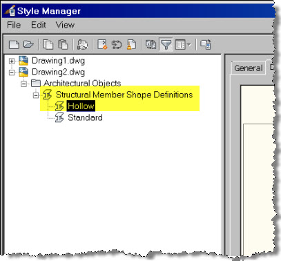
You can also access this through the Ribbon under Manage -> Style & Display -> Style Manager. You will find the Structural Member Shape Definitions under the Architectural Objects category.
- You will see the Style Manager dialog open. In the left pane, right-click on Structural Member Shape Definitions and select New.
-
Type 'Hollow' for the name. It is good practice to use the size of the member cross section as the name. For example: Hollow 600x400.
-
In the right pane, under Shape Geometry:, select Medium Detail.
.jpg)
-
Click the
 icon.
icon. - The Style Manager dialog temporarily closes and you are returned to the drawing screen.
- At the "Select a closed polyline, spline, ellipse, or circle for an outer ring:" prompt, select the outer polyline from the first sketch (with sharp corners) and press Enter.
- At the "Insertion point or [Add ring/Centroid]:" prompt, type "a" and press enter, to choose the "add" option.
- At the "Select a closed polyline, spline, ellipse, or circle for an additional ring:" prompt, select the inner polyline.
- Again, at the "Insertion point or [Add ring/Centroid]:" prompt, type "c" to choose the "centroid" option.
You are now returned to the Style Manager dialog box.
We are finished defining the structural member shape. In the next article, we will proceed to create a structural member style that uses this shape named Hollow. Also, we will explore the creation of composite and tapered columns.