AutoCAD Architecture: A Kick Start
Wall styles and material definitions
In this exercise, we will learn how to use materials to control the display properties of a wall style.
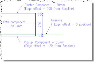
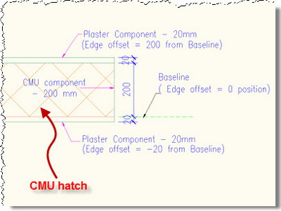
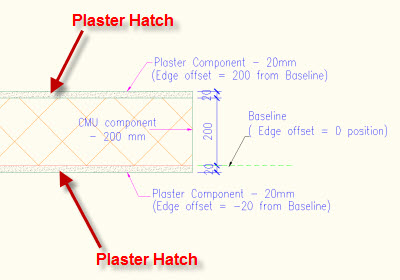
Let us continue from the wall style (P20-CMU200-P20-1h) we created in the Januarylesson. We have three components (the CMU and plaster on both sides) for which we have to apply hatches. Here is a snapshot of the wall style we created earlier.
In the earlier exercise, we specified our own colors for the wall directly through the display properties. But for this exercise, we will ensure that all components of the walls are set to "By material." This is because we are going to allow the material to take control of the wall display. To ensure this:
- In the drawing area, select the wall (of style P20-CMU200-P20-1h), right-click, and select Edit Wall Style. Before doing this, ensure that you have at least drawn one wall in the drawing, which is of style P20-CMU200-P20-1h.
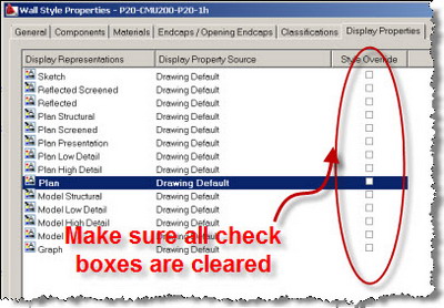
- You will see the Wall Style properties dialog open. Click the Display properties tab.
-
Under Style Override, ensure that all check boxes are clear (i.e., no display representations are overridden).
-
Select Plan under Display representations column and click the Edit Display properties button in the top right corner of the dialog box. You will see the Display Properties dialog open up.
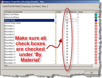
- Ensure that "By material" is checked for all components. Refer to the figure above.
- Click OK to close the Display Properties dialog.
- Repeat the above process for Plan High Detail and Plan Low Detail display configurations.
- Click OK to close the Wall Style Properties dialog box.
Now we need some materials. You can create your own materials, too, but for now, we will look for materials in the content browser.
- Use Ctrl+4 to open the Content Browser.
- Click the Visualization catalog.
- Then click AEC Material Tools - US metric - Masonry - Unit Masonry.
In the fourth page or so, you will see the material 'Masonry.Unit Masonry.CMU.Stretcher.Running'. (I use the metric content library as an example here.)
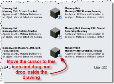
- Drag and drop the material into the drawing area. Refer to the figure above.
- At the "Select a component or an object:" prompt, select the CMU component of the wall. (As you move the cursor near the wall, you can see the CMU component getting highlighted.)
- At the "Apply the material to the style or [this Object]:" prompt, press enter.
You can see the material getting applied to the CMU component of the wall and the hatch for the CMU component appears.
-
Now try to change the display configuration of the drawing from Medium Detail to High Detail, Low Detail, etc. (You can access this at the drawing status bar.)
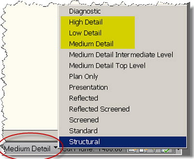
You will see that the hatch scale changes accordingly as you change the display configuration. Now let us proceed to apply a material for the plaster components. This time, we will create our own material definition rather than getting it from library.
- From the Format menu, select Material Definitions. The Style Manager opens up. Under material definitions, you can see the Masonry.Unit Masonry.CMU.Stretcher.Running listed. This is the one you just dragged from the content browser.
- Right-click on Material Definitions and select New.
- For the name, type "Plaster."
- Select the Plaster material in the left pane. In the right pane, click the Display Properties tab.
- Under Display properties, select General Medium Detail.
- Check the check box under Style Override. You will see the "Display properties" dialog open up for the General Medium Detail representation.
- Click the Hatching tab.
- Under pattern, click on "user single."
- The "Hatch pattern" dialog opens up.
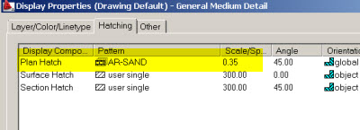
- Select AR-SAND pattern from the predefined group.
- For scale, specify "0.35".
Here, you can see the three types of hatches controlled by the material namely plan, surface, and section hatch.
-
Click 'OK' to close the 'Hatch Pattern' dialog.
-
Click the 'Layer/Color/Linetype' tab.
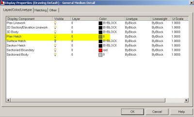
Here, you can see the various components controlled by the material definition like, Plan Linework, 2DSection/Elevation Linework, Plan Hatch, surface hatch, section hatch, sectioned body etc.
Also note that the 'Surface Hatch' component is switched off .This way, we can avoid the display of the AR-SAND hatch on the wall, whenever you switch to a 3d view in a wireframe mode.
- For the plan hatch, change the color to '8'.
Also note that you can control various other properties of the components like Lineweight, LT Scale, orientation of the hatch etc.
- Click OK to close the "Display properties" tab.
- Repeat the same steps above to configure the General High Detail display representation. The only change you will make is to specify a hatch scale of ".2" to the AR-SNAD hatch pattern.
We are done with the material definition creation. Now let's get back to the wall style and use this material for the plaster components.
- Select the wall, right-click, and choose Edit Wall Style.
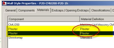
- In the "Wall Style properties" dialog, click the Material tab.
-
For both the Plaster wall components, change the material to Plaster (the material you just created).
- Click OK to close the dialog.
You can see the wall style getting updated in the drawing.
Try changing the drawing Display Configuration to High Detail, Medium Detail, and so on. You will see the plaster hatch change the scale automatically (.35 and 0.2).
Feel free to get back to the material definition and change the scale, color, and orientation of the hatch pattern. Also try to change the colors and lineweight of the "plan line work" component. Play around with both the Masonry.Unit Masonry.CMU.Stretcher.Running and the Plaster material definitions.
I hope I made it clear in a simple and straightforward way. We will see more properties of a Material Definition in the future. See you all next month.

(Discuss this Article! in the HotNews Discussion Forums.)