AutoCAD Architecture 2010 Tips & Tricks
Creating Structural Member Styles Using Custom Member Shape Definitions, Part 2
Welcome back! Let's continue from the previous lesson. Last time, we created a structural member shape named Hollow. Now, we will create a new structural member style that will use this shape.
- Open the drawing in which you created the Hollow member shape. If you haven't created one yet, you can follow the earlier lesson to create one.
-
In the tool palette under the Design tab, right-click on the Column, Beam, or the Brace tool and select Structural member Styles...
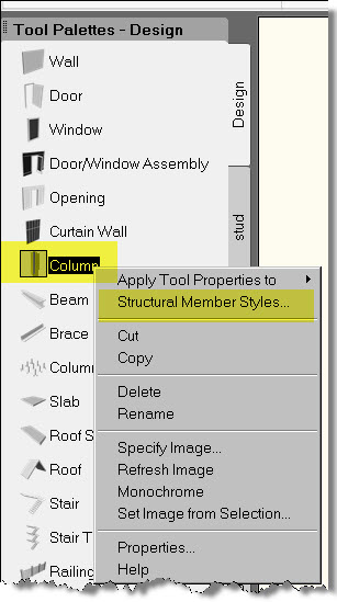
Command line equivalent: memberstyle
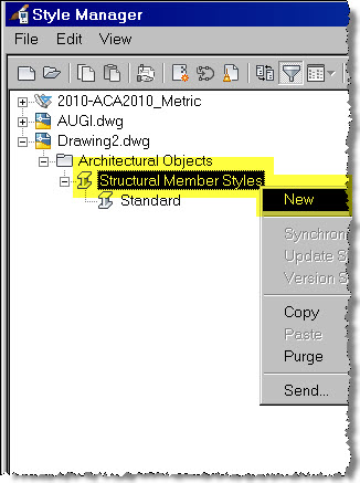
You will see the Style Manager dialog opening up. -
In the left pane, under Architectural Objects, right-click on Structural member Styles, and select new.
-
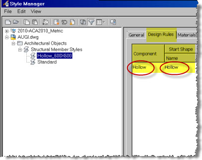
Type a name for the structural member style. Keep the name meaningful. I used the name Hollow_600X600. You can make it as descriptive as you want, depending upon the style you create.
A point to note here is that, even though there are three tools named column, beam, and brace, they all belong to one object type called Structural member. So, any Structural member Style you create could be added as a column, beam, or brace.
- In the right pane, click the Design Rules tab.
- You will see an unnamed component existing by default.
- Click on Unnamed and rename it to Hollow. Again I would like to remind you that when naming shapes, member styles, components, etc., always use meaningful, short names that will help you to easily identify the member and its properties.
- Under the Start Shape column, click on Standard.
- Click on the drop-down arrow.
- You will see the name of the member shape you defined. In this case, Hollow. In case you defined many other member shapes, those will appear in this drop-down list too. Select Hollow. Refer to the figure below.
-
Click OK to close the dialog box.
We just created a structural member style named Hollow 600x600, which is made of a single component named Hollow that uses the shape named Hollow. In this example, the names of the component and the shape are the same. Actually, they can be different.
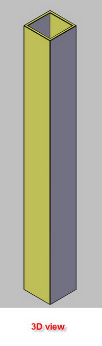
Let's try to add a sample column of this style to see what we have created.
- In the Tool Palettes under the Design tab, click the Column tool (command line equivalent: columnadd)
- Place a column in the drawing area and press enter to finish the command. By default, AutoCAD Architecture places a column made in Standard style. Let's change this to the Hollow 600x600 style which we created just now.
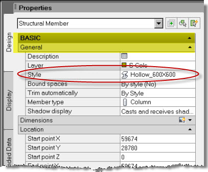
- Select the column you just placed.
- In the Properties palette, make sure the Design tab is selected. If the Properties palette is not visible, use Ctrl+1.
-
Under Basic, and under General, change the style to Hollow 600x600.
- Make sure that Medium Detail display configuration is selected (at the drawing status bar).
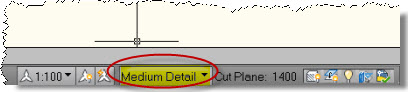
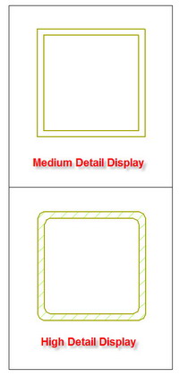
- Now change the display configuration to High Detail and see how the column graphics change to reveal more details.
Observe the way the High Detail configuration uses the shape you defined (with filleted corners) to be used for High Detail using the Membershape command. Once you learn the concepts of display configuration, you can customize the way the column is represented in a high or low detail configuration.
 |
 |
We just learned the basics of creating a simple structural member style that uses a single shape across its cross section. In the next lesson, we will take this a step further and learn to create more complex structural member styles.
Wishing you all Happy Holidays and a fantastic New Year ahead!