AutoCAD Architecture 2010: Radial Grids
Welcome back! In the previous lesson, we learned about creating and modifying rectangular column grids. Let us now take a look at drawing radial grids. We will add a default polar grid and analyze its properties.
I will be using metric examples here. But as you practice, you can follow this article and work on imperial units too.
- Create a new drawing based on the template, 'Aec Model (Metric Ctb).dwt'
-
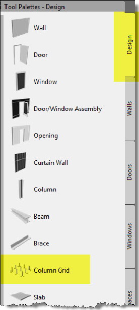
From the Design palette, click on the 'Column Grid' tool. (Command line equivalent : 'Columngridadd' or 'columngrid')
-
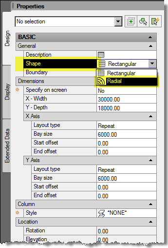
At the 'Insertion point or [WIdth/Depth/XSpacing/YSpacing/XDivide by toggle/YDivide by toggle/Match]:' prompt, before picking a point on the screen, in the Properties palette, select 'Radial' for the shape. Tip: Ctrl+1 to open or close the Properties palette.
- At the ' Insertion point or [Radius/Angle/Inside radius/XSpacing/Bay angle/XDivide by toggle/YDivide by toggle/Match]:' prompt, pick a point on the screen.
- At the 'Rotation or [Radius/Angle/Inside radius/XSpacing/Bay angle/XDivide by toggle/YDivide by toggle/Match] <0.00>:' prompt, press 'Enter' to accept the default value of '0'.You can also enter an angle here to have the grid oriented at an angle.
- Again at the ' Insertion point or [Radius/Angle/Inside radius/XSpacing/Bay angle/XDivide by toggle/YDivide by toggle/Match/Undo]:' prompt, press 'Enter' to finish the command.
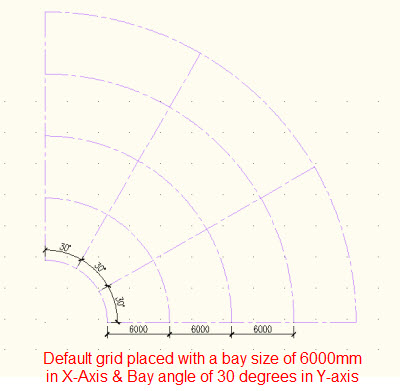
You will see the column grid placed with its default dimensions .We can later modify the column grids in many ways, to suit the project.
Note: Once you place the column grid, you cannot change the shape from radial to rectangular or vice versa.
As you refer the previous article, very similar to the rectangular grid, you can also modify the layout modes of the radial grid, in both the X & Y axis directions. Also, when the layout manual is set to 'Manual', you have complete control of the grips.
Placing columns at all grid intersections
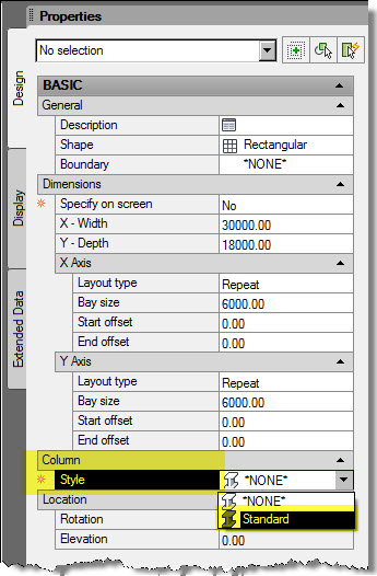
As you add the column grid, before picking a point to place the grid, in the properties palette, under 'Column', select the structural member style you need. By default, it is set to 'None'.
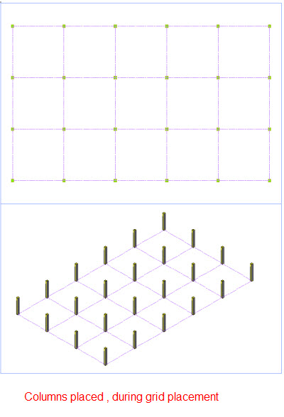
Once columns are placed at all intersections, it is easy for you to remove the ones which are not required and also change the structural member style from one to the other.
Labeling the column grid
Once the column grid is placed:
- Select the grid, right click & select 'Label'. You will see the ' Column grid labeling' dialog box open. The dialog box has two tabs namely 'X-Labeling' & 'Y-Labeling', giving you control on labeling in either directions.
- In the 'X-Labeling' tab, under 'Number', Click the blank entry & type ' A' and press 'Enter'.
You can see that labels are generated for all the grids in the X-Axis. For this to happen, the 'Automatically Calculate Values for Labels' check box should be checked. The default way the labels are generated in an ascending order. You can change this by electing the 'Descending' radio button. Also, by default the labels are generated both in top & bottom for the X-Axis. You can remove the check boxes either for 'Top' or 'Bottom' if you want to label only the top or only the bottom. Refer to the below figure.
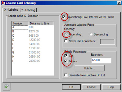
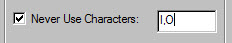
In the above example, the labels are generated from grid 'A' to Grid 'I'. In case you want to avoid certain characters while labeling, you can check the 'Never Use Characters' and key in the characters you don't want to use, separated by commas as in the below figure.
You should do this before you generate the labels. If you already generated the labels you should regenerate the bubbles to reflect the changes:
- Under 'Number', click 'A', the first entry you typed.
- Press 'Enter'
You will see the labels regenerated, respecting the modifications you did. Once you have learned doing the settings in the X-Labeling, you can follow the same procedures to do the settings for the Y-Labeling.
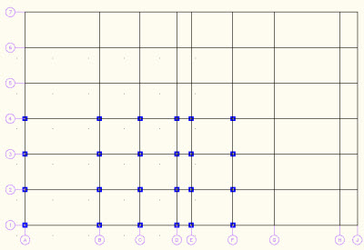
Once you are done with all the settings in the 'Column Grid Labeling' dialog, click OK. In the below figure, I have used labeling in both X and Y directions, but only in the bottom and left.
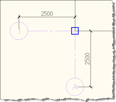
The extension of the labels from the grid is controlled by the value, 'Extension' in the 'Column Grid Labeling' dialog box. Even after you label, if you want to edit this value.
- Select the grid, right click & choose 'Label'.
- Under 'Bubble Parameter' enter the extension value .
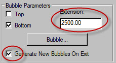
Remember to check the check box 'Generate New Bubbles On Exit'. If you don't, the extension value will not be updated.
Now as you grip edit the grids and move them, you will find that both the labels and the inserted columns move along with the grid. This happens because the columns are anchored to the grid using the 'Node Anchor' feature and the labels are anchored to the grids using the 'Leader Anchor' feature. We will learn more about anchors in the future lessons.
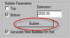
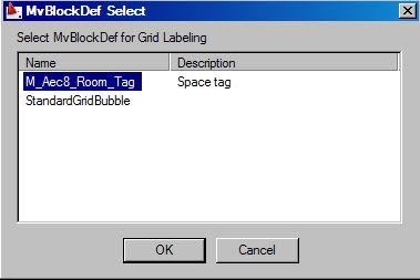
Also note that the default bubble used for labeling is a 'Multiview Block Definition' named 'StandardGridBubble'. If there is a specific 'Multiview Block Definition' created as per CADD standards followed by your company, you can select it by clicking the 'Bubble' button in the 'Column Grid Labeling' dialog box.
This will open the 'MvBlockDef' dialog, from where you can select the defined MV blocks.
We'll see more next month. Keep practicing!