AutoCAD Architecture 2010: Key Features, Part 3
Welcome back to our continuing lessons on the new features of AutoCAD Architecture 2010. This month, I'm going to discuss some of the enhancements for walls, releases 2009 and 2010.
Using the Ctrl key during the layout of a wall
When drawing a wall, before you could pick the other end point of the wall, you can use the Ctrl key to switch the orientation of a wall based on its current justification. For example, from the wall palette, try to add the CMU-190 Rigid-038 Air-050 Brick-090 wall and use the Ctrl key to toggle the orientation of the wall. As this is a toggle key, you can use this repeatedly to cycle through both orientations. This is one useful tool, which allows to change your mind on the fly while laying out a wall.
Using the Shift key during the layout of a wall
Similar to the Ctrl key, when drawing a wall, before you could pick the other end point of the wall, you can press the Shift key to cycle through the different justifications of a wall, such as center/left/right/baseline. This way, you save time instead of changing the justification of the wall through the properties palette later.
Using the Offset option during the layout of a wall
When you draw complex walls with more than one component, at times you need more control during layout, in addition to the justification. For example, when drawing a CMU-190 Rigid-038 Air-050 Brick-090 Furring wall, if you want the center of the CMU component to be along the points you pick, you can use the Offset option by typing 'o' at the command prompt:
Command: WallAdd
Start point or [STyle/Group/WIdth/Height/OFfset/Flip/Justify/Match/Arc]:
End point or [STyle/Group/WIdth/Height/OFfset/Flip/Justify/Match/Arc]: o
Pick a point or offset <0.00>:
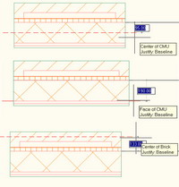
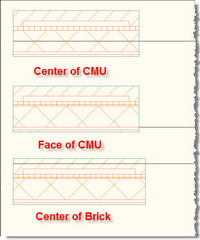
At the "Pick a point or offset <0.00>:" prompt, either key in the offset value you want or hover the mouse over the wall components to select the edge or center of a wall component. You will see assistant lines with a tooltip display to indicate which part of the particular wall component is selected. You can select a wall component's face or center, or the overall center of the wall.
Here is a snapshot of the various offset options you get as you hover the mouse over the wall components.
 |
 |
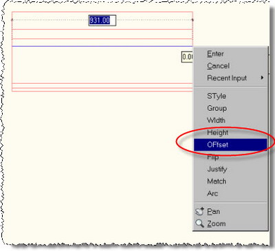
While adding a wall, you can also invoke the offset option by right clicking and selecting the option "Offset."
Using object snaps with wall justification line
With this feature enabled, you can snap to the wall justification line using any of the snap modes such as end, mid, and so on. With this feature disabled, you can snap to any component of the wall. Enabling this feature will force snapping only to the wall justification line and you cannot snap to other components of the wall.
To enable this feature:
-
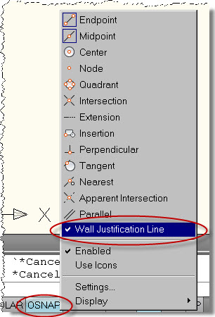
At the drawing status bar, right-click on the Osnap icon/button and make sure that Wall Justification Line is selected.
Alternatively:
- Type 'OS' or 'Osnap' at the command prompt to open the Drafting Setting Dialog Box.
-
Ensure that 'Allow general object snap settings to act upon wall justification line' is checked.
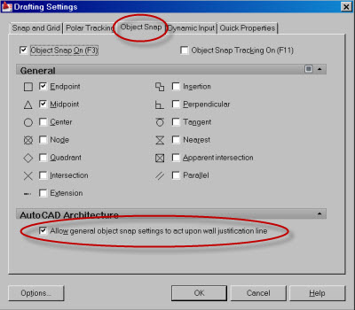
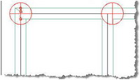
With this option enabled, as you start drawing a new wall segment and when you try to move your cursor near another existing wall, you will see that the justification line is automatically displayed on the existing wall segment and you can use any of the object snaps to snap to he justification line.
The red circles of death and the triangles of tranquility
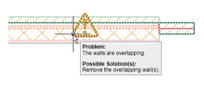
In my earlier articles about walls, I have discussed the red circles that appear, indicating improper cleanup of walls or errors in walls and how to tackle them. Since release 2009, these red circles are replaced with a triangle icon called the Solution Tip Icon, or what I call the "triangles of tranquility."
Moreover, cleanups and graphics are automatically corrected for many situations. The majority of earlier cases, where you would have seen the red markers, are now solved automatically without any need for a corrective trim or fillet. Simply speaking, almost more than a dozen possible wall cleanup situations which could have caused a red circle display are automatically corrected since release 2009. This simply means greater control and peace of mind over complex wall cleanup situations.
 |
 |
You can hover the cursor over the solution tip icon to display a message that describes the problem and provides one or more possible solutions. Some solution tips provide complete instructions for resolving the problem. Keep in mind, however, that these messages are tips rather than guaranteed solutions.
AutoCAD Architecture release 2010 takes the wall cleanup control into another level by allowing you to edit the wall cleanup in place - very similar to how you edit AEC profiles in place. We will discuss this in the next article. Happy summer!!