Revit Fundamentals: Standards Implementation
Welcome to part 2 of a discussion about developing and using standards in the Revit BIM platform. Previously, our intrepid CADD operator delved into researching their AutoCAD and manual drafting standards for line weights. He then customized the Line Weights dialog in Revit to improve on the line variation that is shipped with the software. Following that he got rid of unneeded plot scales, created line patterns and applied the combination into object styles. If this didn’t whet your appetite, I don’t know what will! Now this article continues from instruction given in the previous edition of AEC Edge. If you are just starting here you might want to go review that first.
[Editor’s Note: Read the article in the Fall 2009 issue called: Revit Fundaments: Standards Control by David Harrington]
In this segment we look at elements in the Object Styles dialog and then uncover their relationship with family content. The Object Styles dialog is the largest dialog in Revit but don’t let that scare you. Working with it just requires lots of time and a good deal of patience. It is here, in the Object Styles dialog, that you set the default look of all your views and subsequent drawings.
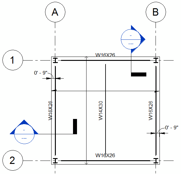
Figure 1- Sample model plan standards per the default template
In Figure 1 we have a small sample plan for a steel framing plan with the out-of-the-box settings. Now reproducing images in a magazine isn’t a perfect science, I have no idea how big my figure will be but you should be able to notice the line weights. Now compare that to Figure 2 and what changed. The beams are a bit thicker and much of everything else for that matter.
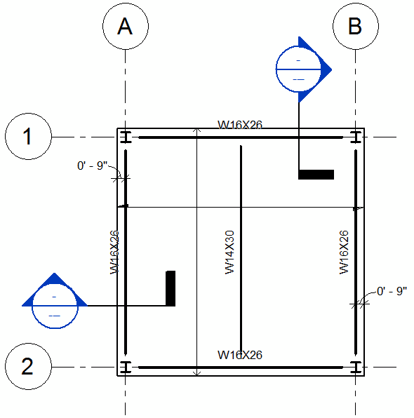
Figure 2- Sample model plan standards customized
So what did I change? The very minimum of course! I changed the projection line weight for Structural Framing > Girder to line weight 10 and Joist to 9. I changed the Structural Columns > Stick Symbols Cut line weight to 9 as well. Lastly I changed the Floors > Projection to line weight 6. That dealt with all the model objects in this plan view. Next, annotation!
The grid line weight is controlled is the Type Properties for the Grid. The default is 1, I changed it to 2. But the circle is controlled back in Object Styles on the Annotation Objects tab. I changed it from 1 to 6. Next is the section marks!
Again we have to go in multiple places to complete the customization. The section cut line is controlled by Object Styles, Annotation Tab, Section Line – make the Projection line weight 8. The outside edge of the section tail is controlled by Section Marks > Thin Lines. Change it from 1 to 8 as well. This should take care of the back end of the section, time for the head. While editing Object Styles change Section Marks Projection line weight to 8 to match the others. When you click OK to close the dialog all lines in the section mark should now be 0.5mm wide.
Lastly we have the dimension style. Pick on a dimension ele- ment and open the Type Properties. First in the Graphics area change the Tick Mark to Diagonal 3/32” and right below that change the Line Weight to 3 (0.18mm). Now bump the Tick Mark Line Weight to 6. Then modify the Dimension Line Ex- tension to 1/16”.
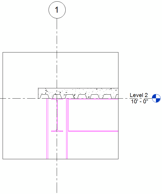
Figure 3- A typical default section view’s appearance
That will wrap up the changes to get this plan looking they way we prefer. Next is dealing with a section view. At the north edge of the plan is a section mark. In Figure 3 this section view is shown. Now it doesn’t look like much, even after all the work we have been doing, largely because the lines in this view generally belong to cut elements and other than columns we have not addressed any cut line weights yet.
So once again we open the Object Styles dialog. You certainly don’t want to go through this effort at the view level, via the Visibility/Graphics dialog, or you will have to repeat the edits with every section. From the Object Styles dialog and the Floors category and change what? Well this is where the previous work described in the Fall issue’s article is beginning to pay off because it is easier to see what is wrong here. From the section view we can see that the floor is black – not magenta. And only one floor category is black so the Cut line weight is the spot to edit. Change that to pen 8. Once you return to the section view the profile of the deck and concrete is now nice and heavy.
Again back to the Object Styles dialog, this time slide on down to Structural Column. Now the column we see is not black and it is not a stick symbol so the slot to change is probably going to be the main Project line weight. Change that to pen 4 and make it black. After the column, on to the beam. Go down to Structural Framing. Here are many, many category slots for framing. The difference is that we are not looking at the beam in a coarse detail level. The main Structural Framing Projection line weight is the one we need, change it to pen 4 and black as well. But we do see 2 beams here, and one is in section. The Cut line weight needs bumping up as well to pen 7 (0.45mm).
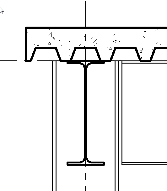
Figure 4- The corrected section components are clear now
As you can see in Figure 4, the various components that make up the steel and deck are significantly more pronounced. Are we done for sections? Not really, in fact, more can be done now for this model itself. And we do have another section in this model and Figure 5 shows the problem.
We modified the Object Style for floors but in the section we looked at, the parallel condition was not visible. In Figure 5 we have other layers in the floor system to correct. Back to the Object Styles dialog and expand Floors. Now depending on your graphic standard you might run into software control limitations – you can’t always do everything you want. I know the magenta line is incorrect and I know from experience that it is the Common Edge Cut between the deck and the slab. So we will bump that to pen 4 and black. I would prefer that the thin line just below the common edge be hidden – I have yet to find a way to do that.
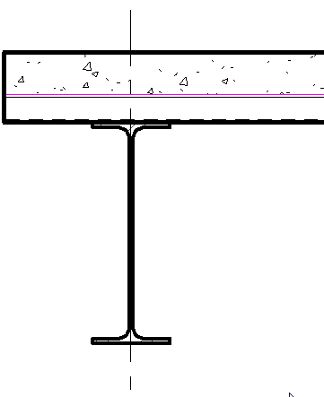
Figure 5- Additional components of a floor needing adjustment
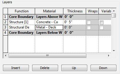
Figure 6- Layers area of the Edit Assembly dialog
So now the section looks pretty good. If I had to complain it would be that technically the concrete should be in the deck area because of section looks to be cutting through a low flute location. Can I get hatch there? Yes, but it is in another area. If we edit the Floor Type properties and go into the Structure we can assign a material for the deck itself. As shown in Figure 6, in the Layers portion of the Edit Assembly dialog is a edit slot that opens up the Material dialog. I know it seems like an odd way to control this, but it gets the job done. Now as shown in Figure 7, the floor in section looks presentable.
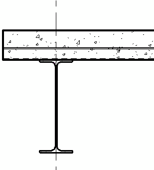
Figure 7- The completed changes to the Object Styles
Now of course this is not the end of this effort. We have taken care of a small percentage of the things to customize in Revit. The cool part is that we are addressing things in a one-at-a-time process. It does take more time but it lets you discover much more about the software. You will learn all the little bits that control how your model and drawings look. As long as you have a solid skeleton in which to build on this method is certainly an option to the “do it all in one sitting”. Who really has time for that? Until next time.