


AUGI HotNews

Monthly email newsletter disseminates information about upcoming events, special offers, general announcements, columns and feature articles designed to deepen your understanding and enhance your use of Autodesk products.
View HotNews Issues
Surveys and Polls
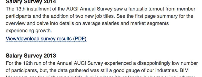
We are our greatest resource when it comes to finding out about the state of our respective industries. We do that every year by asking our members to participate in an anonymous survey of their salaries, raises and perceptions of job security.